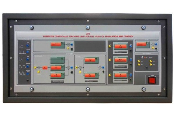
Bancada Didática de Controle de Levitação Magnética Edibon RYC CLM
Preço sob consulta
A Unidade de Ensino Controlada por Computador para o Estudo de Regulação e Controle, “RYC”, permite que os alunos simulem um sistema integrador, um sistema de primeira ordem e um sistema de segunda ordem e os regulem com um controlador PID ou compensador Lead & Lag. A unidade também permite simular perturbações e compensações para analisar a resposta do sistema.
Uma ampla gama de aplicações: Módulo Servo Motor DC, Módulo Bola e Feixe, etc. para trabalhar com a unidade “RYC” estão disponíveis para estudar uma resposta real dos sistemas de controle para complementar o Estudo de regulação e controle em tempo real.
Esta Unidade Controlada por Computador é fornecida com o Sistema de Controle de Computador EDIBON (SCADA) e inclui: A própria unidade + uma Caixa de Interface de Controle + uma Placa de Aquisição de Dados + Pacotes de Software de Controle de Computador, Aquisição de Dados e Gerenciamento de Dados, para controlar o processo e todos parâmetros envolvidos no processo.
ESPECIFICAÇÕES:
RYC. Unit:
Unit:
Metallic box.
Diagram in the front panel with distribution of the elements similar to the real one.
Reference signals module:
This module allows to generate four different
types of signals: step, square, ramp and sine.
The frequency and amplitude of the signals can
be adjusted through the computer.
Step output. Square output. Ramp output.
Sine output.
Step: amplitude: 0 V to 5 V, frequency: 0Hz
to 200 Hz.
Square: amplitude: ±10 V, frequency: 0Hz to
200 Hz.
Ramp: amplitude: ±10 V, frequency: 0Hz to
200 Hz.
Sine: amplitude: ±10 V, frequency: 0Hz to
200 Hz.
Frequency sweep: this module performs a
frequency sweep needed for calculating the
Bode plot.
PID controller module:
This module is subdivided into proportional, integrative and derivative blocks. The module allows
to adjust each parameter independently from the computer:
P controller: Kc: -10 to +10. I controller: Ti: 0 to 100 s. D controller: Td: 0 to 100 s.
Sample time: 0.1 to 100 ms.
Lead/Lag compensator:
This module represents a compensator system in the Laplace domain. The system allows to modify
the zero, the pole and the gain of the compensator through the computer:
K lead: 1 to 100 s. K lag: 1 to 100 s. Gain: 1 to 10. Sample time: 0.1 to 100 ms.
Integrator system:
This module represents and integrator system in the Laplace domain. The system allows to modify
the gain and the saturation valve of the system through the computer:
Gain: -10 to 10.
Saturation: -10 to 10.
First order system:
This module represents a first order system in the Laplace domain. The system allows to modify
the time constant of the system through the computer. The gain can be also adjusted using the
computer:
Gain: 0 to 10. Time constant T: 0 to 100 s.
Second order system:
This module represents a second order system in Laplace domain. The system allows to modify
through the computer the three parameters of the system: gain, damping coefficient and the
natural frequency:
Gain: 1 to 10.
Damping coefficient x: 0 to 1.5 in steps of 0.1.
Natural frequency (w n): 1Hz to 2 p*100 rad/s (100 Hz).
Perturbation module:
This module allows to insert disturbances in the systems. The perturbation can be inserted in
different places of the control loop:
Perturbation value: -10 to 10.
Offset module:
This module allows to add an offset to the input signal.
Offset value: -10 to 10.
Analog Inputs:
This module is provided with 4 analog inputs. The inputs are used to visualize different signals in
the computer.
Connector to computer.
Control Interface included.
RYC-CLM. Magnetic Levitation Control Module.
The “RYC-CLM” Magnetic Levitation Control module has been designed to study a practical control
system.
The “RYC-CLM” module consists of two main components: the “RYC-CLM” apparatus and the “RYCCLM” interface box. The “RYC-CLM” apparatus contains all the sensors and actuators such as electromagnet, current sensor, position sensor, etc. The “RYC-CLM” interface box contains all necessary
components for power supplying, signal conditioning, etc.
The components are used in conjunction with the “RYC” unit to control the vertical position of the
metallic ball through the control of the feeding current of the electromagnet.
The system allows to insert disturbances manually
Specifications:
Metallic structure.
Electromagnet.
Current sensor of the feeding current of the electromagnet.
Coil driver circuit.
Steel ball.
Ball position sensor.
Dimensions: 400 x 400 x 300 mm. approx. (15.74 x 15.74 x 11.81 inches approx.).
Weight: 12 Kg. approx. (26 pounds approx.).


